TRA INING
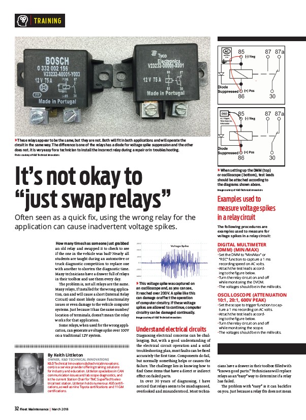
» These relays appear to be the same, but they are not. Both will fit in both applications and will operate the
circuit in the same way. The difference is one of the relays has a diode for voltage spike suppression and the other
does not. It is very easy for a technician to install the incorrect relay during a repair or in troubleshooting.
Photo courtesy of K&D Technical Innovations
How many times has someone just grabbed
an old relay and swapped it to check to see
if the one in the vehicle was bad? Nearly all
students are taught during an automotive or
truck diagnostic competition to replace one
with another to shorten the diagnostic time.
Many technicians have a drawer full of relays
in their toolbox and use them every day.
Th e problem is, not all relays are the same.
Many relays, if installed for the wrong application,
can and will cause a short (Internal Relay
Circuit) and most likely cause functionality
issues or even damage to the vehicle computer
systems. Just because it has the same number/
location of terminals, doesn’t mean the relay
works for that application.
Some relays, when used for the wrong application,
can generate a voltage spike over 100V
on a traditional 12V system.
32 Fleet Maintenance | March 2018
Understand electrical circuits
Diagnosing electrical concerns can be challenging.
But, with a good understanding of
the electrical circuit operation and a solid
troubleshooting plan, most faults can be fi xed
accurately the fi rst time. Components do fail,
but normally something helps or causes the
failure. Th e challenge lies in knowing how to
fi nd these items that have a direct or indirect
eff ect on failed parts.
In over 30 years of diagnosing, I have
noticed that relays seem to be misdiagnosed,
overlooked and misunderstood. Most technicians
Examples used to
measure voltage spikes
in a relay circuit
The following procedures are
examples used to measure for
voltage spikes in a relay circuit:
DIGITAL MULTIMETER
(DMM) (MIN/MAX)
• Set the DMM to “Min/Max” or
“REC” function to capture a 1 ms
recording speed on AC volts.
• Attach the test leads according
to the figure below.
• Turn the relay circuit on and off
while monitoring the DVOM.
• The voltages should be in the millivolts.
OSCILLOSCOPE (ATTENUATION
10:1, 20:1, 600V PEAK)
• Set the scope to trigger function to capture
a 1 ms recording on AC volts.
• Attach the test leads according
to the figure below.
• Turn the relay circuit on and off
while monitoring the scope.
• The voltages should be in the millivolts.
have a drawer in their toolbox fi lled with
“known good parts.” Technicians will replace
relays as an “easy” way to determine if a relay
has failed.
Th e problem with “easy” is it can backfi re
on you. Just because a relay fi ts does not mean
It’s not okay to
“just swap relays”
Often seen as a quick fi x, using the wrong relay for the
application can cause inadvertent voltage spikes.
By Keith Littleton
OWNER, K&D TECHNICAL INNOVATIONS
K&D Technical Innovations (kdtechnicalinnovations.
com) is a service provider offering training solutions
for industry and education. Littleton specializes in CAN
communication issues and lab scope diagnostics, and
is the current Station Chair for TMC SuperTech’s electrical
test station. Littleton holds numerous ASE certifications,
as well as nine Toyota certifications and 11 GM
certifications.
» When setting up the DMM (top)
or oscilloscope (bottom), test leads
should be attached according to
the diagrams shown above.
Image courtesy of K&D Technical Innovations
» This voltage spike was captured on
an oscilloscope and, as you can see,
it reached over 200V. A spike like this
can damage or affect the operation
of computer circuitry. If these voltage
spikes are allowed to continue, computer
circuitry can be damaged continually.
Image courtesy of K&D Technical Innovations
/kdtechnicalinnovations.com
/kdtechnicalinnovations.com
/kdtechnicalinnovations.com