REVENUE
GENERATING
OPPORTUNITIES
Electrical Work
ground locations in order to perform
necessary tests.
System and component specifications
will allow you to test individual
components to determine if they are
functioning and have not been damaged
in the fire.
Testing solenoids to assure resistance
is within specifications can be
done with your digital multimeter. Solenoids
should also be tested by removing
them from the vehicle and bench testing
them to make sure they open and
close completely when applying power
and ground. These tests can be easily
accomplished with a Power Probe which
allow you to apply power and ground
with the flip of switch.
Another critical step in determining
the extent of damage is to inspect
all connectors. This step starts with a
visual inspection of the housing and
pins to see if there is any discoloration
or deformities. It is also necessary to use
a pin tension tool to make sure heat has
not weakened the ability of a terminal
to form a tight connection to its’ mating
pin. These tools are made up of a male
pin that has the same diameter of the
original connector and is used by sliding
it into the female terminal to make sure
sufficient drag is felt. Terminals that do
not have the correct tension will create
heat and a subsequent failure and will
require replacement.
Step 2: Repair wiring damage
Take these steps into consideration
when forming your repair plan:
Once you have determined the
extent of the damage including which
parts and wires will need replacing,
you will need to determine the best
way to perform the wiring repairs. This
includes making the determination if a
complete new or used harness would be
preferred over repairing the existing one.
If connector mating pins require
removal from their housing, use a connector
pin removing tool to remove pins
from their mating housings. These tools
will allow you to remove the pins without
44 PTEN DECEMBER 2017 www.VehicleServicePros.com
damaging the pin or housing in
order to be reused.
Pay attention to the routing of harnesses
prior to removal to make sure
any splices will be made in areas that
are not too close to components or in a
curved area.
If only a small area of wiring is
damaged, you may be able to cut out
the burned sections and use splice connectors
and crimp them in. Personally, I
am not a fan of crimp splice connectors
unless they are the ones that are filled
with solder and also use a built-in heat
shrink compound. These connections
provide a secure water-tight connection
that will remain trouble-free.
If there is extensive damage requiring
multiple wire splices, it is usually
better to remove the harness completely
from the vehicle. With the harness
removed you will be able to lay it out
and install splices in a staggered position.
If all the splices are laid out at the
same point, the spliced area becomes a
much larger diameter than original and
may be difficult to work with. With the
wiring harness removed from the vehicle
it is also much easier to install protective
loom and tape.
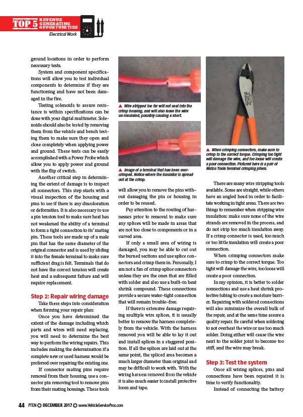
When crimping connectors, make sure to
crimp to the correct torque. Crimping too tight
will damage the wire, and too loose will create
a poor connection. Pictured here is a pair of
Matco Tools terminal crimping pliers.
There are many wire stripping tools
available. Some are straight, while others
have an angled head in order to facilitate
working in tight areas. There are two
things to remember when stripping wire
insulation: make sure none of the wire
strands are removed in the process, and
do not strip too much insulation away.
If a crimp connector is used, too much
or too little insulation will create a poor
connection.
When crimping connectors make
sure to crimp to the correct torque. Too
tight will damage the wire, too loose will
create a poor connection.
In my opinion, it is better to solder
connections and use a heat shrink protective
tubing to create a moisture barrier.
Repairing with soldered connections
will also minimize the overall bulk of
the repair, and at the same time assure a
quality repair. Be careful when soldering
to not overheat the wire or use too much
solder. Doing either will cause the wire
next to the solder joint to become too
stiff, and the wire may break.
Step 3: Test the system
Once all wiring splices, pins and
connections have been repaired it is
time to verify functionality.
Instead of connecting the battery
Wire stripped too far will not seat into the
crimp housing, and will also leave the wire
un-insulated, possibly causing a short.
Image of a terminal that has been overcrimped.
Notice where the insulator is spread
out at the crimp.
/www.VehicleServicePros.com